Internal Architecture and Features of the 8086 Microprocessor
The 8086 microprocessor uses CISC architecture, meaning it supports many complex instructions. It has a 20-bit address bus that can access up to 1 MB of memory and a 16-bit data bus for transferring data.
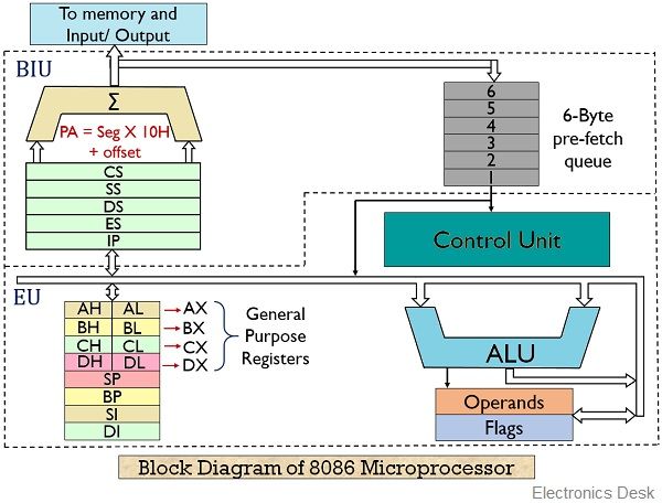
Bus Interface Unit (BIU)
The BIU (Bus Interface Unit) handles all data and address transfers for the EU (Execution Unit). It sends out addresses, fetches instructions, reads data from memory or ports, and writes data to memory or ports. It mainly consists of two parts: the instruction queue and the segment registers.
The BIU can store up to 6 bytes of instructions in a queue using the FIFO (First In, First Out) method. When the EU is ready for the next instruction, it reads it directly from this queue. This helps speed up program execution by allowing instruction fetching and execution to happen at the same time. This process is called pipelining.
The BIU has a special unit to generate a 20-bit address. It uses four segment registers to hold the upper 16 bits of the starting addresses of four memory segments: code, data, stack, and extra. The 8086 divides its 1 MB memory into segments, each up to 64KB in size.
Code segment register and instruction pointer (IP):
The CS (Code Segment) register holds the starting address of the current code segment. The IP (Instruction Pointer) holds the offset or distance to the next instruction. By adding the CS address and the IP offset, the 8086 gets the exact address of the instruction to be fetched for execution.
Data Segment: The data segment contains the starting address of a program’s data segment. Instructions: Use this address to locate data. This address, plus an offset value in an instruction, causes a reference to a specific byte location in the data segment.
Stack Segment: The Stack Segment (SS) holds the starting address of the stack. The Stack Pointer (SP) gives the offset within this segment. Together, SS and SP point to the current location in the stack being accessed.
Extra Segment: The Extra Segment (ES) is used for handling memory addresses during string operations. String instructions use the ES register along with the Destination Index (DI) to calculate the 20-bit physical address.
Execution Unit (EU): The EU decodes and executes the instructions. The EU contains an arithmetic and logic unit (ALU), a control unit, and a number of registers. These features provide for the execution of instructions and arithmetic and logical operations. It has nine 16-bit registers which are AX, BX, CX, DX, SP, BP, SI, DI, and the flag. The first four can be used as 8 8-bit registers (AH, Al, BH, BL, CH, DH, DL).
AX register: The AX register is a 16-bit accumulator, and AL is its lower 8-bit part. Input/output (IN or OUT) instructions use AX for 16-bit data and AL for 8-bit data when transferring data to or from an I/O port.
BX register: The BX register is called the base register because it can be used to help calculate memory addresses. It is similar to the H and L registers in the 8085. BX can also work with DI or SI for special addressing methods.
CX register :The CX register is called the counter register because it is used by instructions like SHIFT, ROTATE, and LOOP to count how many times to repeat an operation.
DX register: The DX register is called the data register. It is used in some input/output operations. For multiplication and division of large values, DX and AX work together as a pair. DX is the lower 16 bits of the 32-bit EDX register.
Stack Pointer (SP) and Base Pointer (BP): The Stack Pointer (SP) and Base Pointer (BP) are used to access data in the stack segment. SP acts as an offset in the stack and changes automatically during PUSH and POP instructions. BP holds an offset used by instructions that access data using based addressing mode.
Index register: The two index registers, SI (Source Index) and DI (Destination Index), are used for indexed addressing. String instructions use SI with the DS segment for the source address and DI with the ES segment for the destination address.
Flage: The 8086 has nine flags, each 1 bit. Six are status flags and three are control flags. The programmer can turn the control flags on or off.
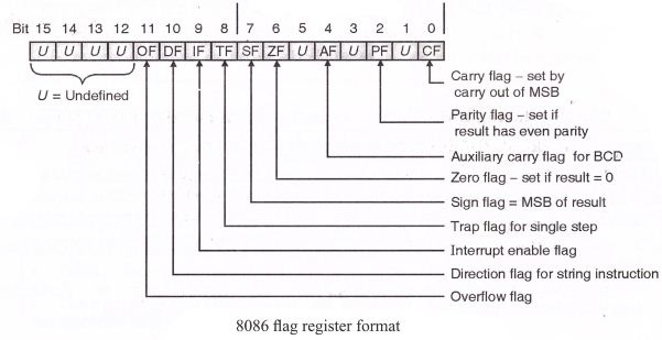
Flag Register of 8086 Microprocessop:
The 8086 flag register has 16 bits, but only 9 of them are active (used). The other 7 bits are marked as ‘U’, meaning they are undefined and not used.These 9 active flags are divided into two types:
- 6 Status Flags
- 3 Control Flags
Status Flags (Show the result of operations)
1. Carry Flag (CY)
- This flag is set (turned ON) if there’s a carry out or borrow from the most significant bit (MSB) during an operation.
- For 8-bit operations, this is bit D7.
- For 16-bit operations, it’s bit D15.
2. Parity Flag (PF)
- This flag is set if the result has even parity (even number of 1s in the binary result).
- If the number of 1s is odd, the flag is cleared (OFF).
- It’s mainly used in error checking during data transfer.
3. Auxiliary Carry Flag (AC)
- This flag is set if there’s a carry from the lower 4 bits (nibble) of a result.
- It’s used in some special 8-bit operations like DAA and DAS.
4. Zero Flag (ZF)
5. Sign Flag (SF)
- This flag is set if the MSB (most significant bit) of the result is 1, which means the result is negative in signed number operations.
6. Overflow Flag (OF)
- This flag is set if the result of a signed operation is too large to be stored in the number of bits available.
- You can check for this using the INTO (Interrupt on Overflow) instruction.
Control Flags (Used to control how the CPU works)
1. Trap Flag (TF)
- This flag is used to turn on single-step mode (also called trace mode).
- In this mode, the processor stops after each instruction so the program can be debugged step-by-step.
2. Interrupt Enable Flag (IF)
- This flag is used to enable or disable external interrupts (INTR).
- If the flag is set, the CPU will respond to external interrupts.
- If it is cleared, the CPU will ignore external interrupt requests.
3. Direction Flag (DF)
- This flag controls the direction of data movement in string operations.
- If it is set, the CPU processes strings from high memory to low memory (auto-decrement).
- If it is cleared, it processes strings from low memory to high memory (auto-increment).
SEGMENT AND OFFSET ADDRESS:
- Segments are special areas defined in a program for containing the code, data and stack.A segment begins on a paragraph boundary. A segment register is of 16 bits in size and contains the starting address of a segment.
- A segment begins on a paragraph boundary, which is an address divisible by decimal 16
or hex 10. Consider a DS that begins at location 038EOH. In all cases, the rightmost hex digit is zero, the computer designers decided that it would be unnecessary to store the zero the zero digit in the segment register. Thus 038E0H is stores in register as 038EH. - The distance in bytes from the segment address to another location within the segment is expressed as an offset or displacement. Suppose the offset of 0032H for above example of data segment. Processor combines the address of the data segment with theoffset as:
- SA: OA (segment address: offset address)
038E: 0032 H = 038E * 10 +0032
= 038EO + 0032Physical address = 03912H
Instructions in 8086 Microprocessor
The 8086 microprocessor supports a wide variety of instructions used to perform tasks such as data movement, arithmetic operations, logical operations, control flow, and more. These instructions are categorized based on their functionality.
1. Data Transfer Instructions: Data Transfer Instructions in the 8086 microprocessor are used to transfer data between registers, memory, and I/O ports. These instructions include operations like MOV, PUSH, POP, IN, and OUT without modifying the data content.
Examples:
MOV: Transfer dataPUSH: Push onto stackPOP: Pop from stackXCHG: Exchange dataIN: Input from portOUT: Output to port
MOV AX, BX ; Copy BX into AX
PUSH AX ; Push AX onto stack
POP BX ; Pop value into BX
2. Arithmetic Instructions: Arithmetic Instructions are used to perform basic mathematical operations such as addition, subtraction, multiplication, and division. In the 8086 microprocessor, examples include ADD, SUB, MUL, and DIV.
Examples:
ADD: AdditionSUB: SubtractionMUL: Unsigned multiplicationIMUL: Signed multiplicationDIV: Unsigned divisionIDIV: Signed divisionINC: IncrementDEC: Decrement
ADD AX, BX ; AX = AX + BX
SUB CX, 1 ; CX = CX - 1
MUL BX ; AX = AX * BX
3. Logical Instructions: Logic Instructions are used to perform bitwise logical operations on data, such as AND, OR, XOR, and NOT. In the 8086 microprocessor, common logic instructions include AND, OR, XOR, and NOT.
Examples:
AND: Logical ANDOR: Logical ORXOR: Logical XORNOT: Bitwise NOTTEST: AND (affects flags only)
AND AL, 0F0H ; Clear lower 4 bits
OR AL, BL ; Set bits from BL
4. Control Transfer Instructions: Control Transfer Instructions are used to change the flow of execution in a program. In the 8086 microprocessor, these include jumps (JMP), calls (CALL), returns (RET), and conditional branches (like JE, JNE, JC). They are mainly divided into two types:
Unconditional Transfer Instructions
- These instructions always change the program flow.
- Examples:
JMP – Unconditional jump to a specified location.CALL – Calls a subroutine and saves the return address on the stack.RET – Returns from a subroutine to the saved address.INT – Calls an interrupt service routine.- 2 . Conditional Transfer Instructions
- These instructions change the flow only if a specific condition is met, usually based on the status of flags (e.g., Zero Flag, Carry Flag).
- Examples:
JE / JZ – Jump if equal / zeroJNE / JNZ – Jump if not equal / not zeroJC – Jump if carryJNC – Jump if no carryJG, JL, JGE, JLE – Jump based on greater/lesser comparisons
5. Loop Instructions: Loop Instructions in the 8086 microprocessor are used to repeat a block of code a specific number of times. They automatically update the CX register, which acts as a counter.
Example:
LOOP: loop until complete
LOOPE: Loop while equal
LOOPZ: loop while zero
LOOPNE: loop while not equal
LOOPNZ: loop while not zero
String Instructions in the 8086 microprocessor are used to perform operations on strings of data stored in memory. They work with the SI (Source Index), DI (Destination Index), and CX (Counter) registers, often in combination with the REP prefix for repeated execution.
Common String Instructions:
- MOVSB / MOVSW – Move byte/word from source to destination.
- LODSB / LODSW – Load byte/word from source into the accumulator (AL/AX).
- STOSB / STOSW – Store byte/word from the accumulator into a destination.
- SCASB / SCASW – Compare the accumulator with a byte/word in memory.
- CMPSB / CMPSW – Compare bytes/words from source and destination strings.
- REP – Repeat the following string instruction while CX ≠ 0.
6.Flag Manipulation Instructions:Flag Manipulation Instructions in the 8086 microprocessor are used to set, clear, or toggle specific flags in the flag register. These instructions help control the status of the processor for decision-making.
Common Flag Manipulation Instructions:
- STC – Set Carry Flag (CF) to 1.
- CLC – Clear Carry Flag (CF) to 0.
- CMC – Complement (toggle) Carry Flag (CF).
- STD – Set Direction Flag (DF) to 1 (used in string operations).
- CLD – Clear Direction Flag (DF) to 0.
- STI – Set Interrupt Flag (IF) to enable interrupts.
- CLI – Clear Interrupt Flag (IF) to disable interrupts.
Machine Control Instructions :Machine Control Instructions in the 8086 microprocessor are used to control the processor’s operation and system-level functions.
Common Machine Control Instructions:
- HLT – Halts the processor until the next external interrupt.
- NOP – No operation; the processor does nothing for one clock cycle.
- WAIT – Pauses the processor until the Test (TEST) input pin is active.
- LOCK – Ensures exclusive use of shared memory in multiprocessor systems during certain instructions.
Operators in 8086 Assembly Language:
In 8086 assembly programming, operators are used in expressions to perform operations on data such as arithmetic calculations, logical operations, and data manipulation. These operators are essential for writing instructions that manipulate registers, memory, and immediate values.
Types of Operators in 8086 Assembly
1.Arithmetic operators:Arithmetic operators in 8086 assembly language are instructions used to perform basic mathematical operations like addition, subtraction, multiplication, division, increment, and decrement on numbers stored in registers or memory. These operators help the CPU do calculations needed in a program.
Common Arithmetic Operators in 8086:
- ADD — Adds two numbers.
- SUB — Subtracts one number from another.
- MUL — Multiplies unsigned numbers.
- IMUL — Multiplies signed numbers.
- DIV — Divides unsigned numbers.
- IDIV — Divides signed numbers.
- INC — Increases a number by 1.
- DEC — Decreases a number by 1.
- NEG — Changes a number to its negative value.
2.Logical Operators: Logical operators in 8086 assembly language perform bitwise operations on data. They work on the individual bits of a number, allowing you to manipulate or test bits.
Common Logical Operators in 8086:
- AND — Performs a bitwise AND operation. The result has a bit set to 1 only if both corresponding bits in the operands are 1.
- OR — Performs a bitwise OR operation. The result has a bit set to 1 if at least one of the corresponding bits is 1.
- XOR — Performs a bitwise exclusive OR operation. The result has a bit set to 1 if only one of the corresponding bits is 1 (but not both).
- NOT — Performs a bitwise NOT operation. It inverts all bits (changes 1s to 0s and 0s to 1s).
3.Shift and Rotate operators : Shift and Rotate operators in 8086 assembly language are used to move bits within a register or memory location. These instructions are useful for bit manipulation, multiplication/division by powers of 2, and encryption algorithms. Example
SHL (Shift Left)SHR (Shift Right)SAL (Shift Arithmetic Left)SAR (Shift Arithmetic Right)ROL (Rotate Left)ROR (Rotate Right)
4.Comparison Operators in 8086
In 8086 assembly language, comparison operators are used to compare two values. They do not change the values, but they set the flags in the FLAGS register (like Zero Flag, Sign Flag, Carry Flag, etc.), which can then be used for conditional jumps.
Common Comparison Instructions:
1. CMP (Compare)
- Compares two operands by subtracting the second operand from the first.
- It does not store the result, but it updates the flags.
- Syntax:
CMP operand1, operand2
(Internally: operand1 - operand2)
Coding in Assembly language:
Assembly language programming language has taken its place in between the machine
language (low level) and the high-level language.
- A high-level language’s one statement may generate many machine instructions.
- Low-level language consists of either binary or hexadecimal operations. One symbolic
statement generates one machine-level instruction.
Advantage of ALP
- They generate small and compact execution module.
- They have more control over hardware.
- They generate an executable module and run faster.
Disadvantages of ALP:
- Machine dependent.
- Lengthy code
- Error-prone (likely to generate errors).
Assembly language features:
The main features of ALP are program comments, reserved words, identifiers, statements, and directives that provide the basic rules and framework for the language.
Program comments:
- The use of comments throughout a program can improve its clarity.
- It starts with a semicolon (;) and terminates with a new line. E.g.
ADD AX, BX ; Adds AX & BX
Identifiers:
- An identifier (or symbol) is a name that applies to an item in the program that is expected to be referenced.
- Two types of identifiers are Name and Label.
- Name refers to the address of a data item, such as NUM1 DB 5, COUNT DB 0
- Label refers to the address of an instruction.
- E.g.: MAIN PROC FAR
- L1: ADD BL, 73
Reserved words:
- Certain names in assembly language are reserved for their own purpose to be used only under special conditions and include.
- Instructions : Such as MOV and ADD (operations to execute)
- Directives: Such as END, SEGMENT (information to assembler)
- Operators: Such as FAR, SIZE
- Predefined symbols: such as @DATA, @ MODEL
Statements:
- ALP consists of a set of statements with two types
- Instructions, e. g. MOV, ADD.
- Directives, e. g. define a data item.
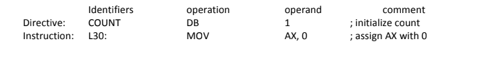
Directives:
The directives are the number of statements that enable us to control the way in which the source program is assembled and lists. These statements, called directives, act only during the assembly of a program and generate no machine-executable code. The different types of directives are:
1) The page and title listing directives: The page and title directives help to control the format of a listing of an assembled program. This is their only purpose, and they have no effect on the subsequent execution of the program.The page directive defines the maximum number of lines to list as a page, and the
maximum number of characters per line.
PAGE [Length] [Width]
Default: Page [50][80]
TITLE gives the title and places the title on the second line of each page of the program. TITLE text [comment].
2) SEGMENT directive
It gives the start of a segment for stack, data, and code.
- Seg-name Segment [align][combine][‘class’][Seg-name ENDS]
- Seg-name ENDS
- Segment name must be present, must be unique, and must follow assembly language naming conventions.
- An ENDS statement indicates the end of the segment.
- Align option indicates the boundary on which the segment is to begin; PARA is used to align the segment on a paragraph boundary.
- The combine option indicates whether to combine the segment with other segments when they are linked after assembly. STACK, COMMON, PUBLIC, etc are combined types.
- Class option is used to group related segments when linking. The class code for the code segment, the stack for the stack segment, and the data for the data segment.
3) PROC Directives
The code segment contains the executable code for a program, which consists of one or
more procedures, defined initially with the PROC directives and ended with the ENDP
directive.
PROC – name PROC [FAR/NEAR]
…………….
…………….
…………….
PROC – name ENDP
- FAR is used for the first executing procedure, and the rest of the procedures call will be NEAR.
- The procedure should be within the segment.
4) END Directive
- An END directive ends the entire program and appears as the last statement.
- ENDS directive ends a segment and ENDP directive ends a procedure. END PROC-Name
5) ASSUME Directive
- An .EXE program uses the SS register to address the stack, DS to address the data
segment and CS to address the code segment. - Used in conventional full segment directives only.
- The assume directive is used to tell the assembler the purpose of each segment in the
program. - Assume SS: Stack name, DS: Data Segname CS: codesegname
6) Processor directive
- Most assemblers assume that the source program is to run on a basic 8086 level computer.
- Processor directive is used to notify the assembler that the instructions or features introduced by the other processors are used in the program. E.g. .386 – program for 386 protected mode.
7) Dn Directive (Defining data types)
Assembly language has directives to define data syntax [name] Dn expression The Dn directive can be any one of the following:
DB Define byte 1 byte
DW Define word 2 bytes
DD Define double 4 bytes
DF defined farword 6 bytes
DQ Define quadword 8 bytes
DT Define 10 bytes 10 bytes
Assembling, Linking and Executing
1.Assembling
- Assembling is the process of changing a source program into an object program, but only if there are no syntax errors. It creates a temporary file called a .obj file or module.
- It also calculates the memory address (offset) for each piece of data in the data section and for each instruction in the code section.
- A header is added to the .obj file, which contains some incomplete addresses needed later.
- If there is a syntax error, the assembler will show an error and will not create the object file.
- The assembler usually creates three files:
.obj, .lst, and .crf. The last two are optional and may be created during the process. - For small programs, a programmer can assemble the code manually by converting each instruction (mnemonic) into machine code using a lookup table.
- The assembler reads each instruction as text (ASCII characters) and translates it into the correct machine code.
Assembler Types: There are two types of assemblers:
a) One-pass assembler:
- This type of assembler reads the assembly language program only once and directly converts it into object code at the same time.
- This assembler has the program of defining forward references only.
- The jump instruction uses an address that appears later in the program during scan; in that case, the programmer defines such addresses after the program is assembled.
b) Two pass assembeler:
A two-pass assembler reads the assembly language program two times (in two passes) to convert it into object code.
- First Pass: It reads the entire program to identify all labels and calculate their addresses. It stores this information in a symbol table but does not generate machine code yet.
- Second Pass: It reads the program again and converts each instruction into machine code using the symbol table created in the first pass.
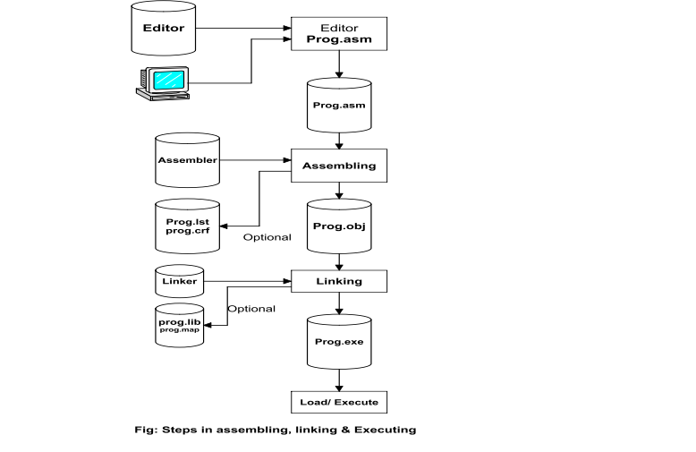
2. Linking:
Linking is the process of combining one or more object files to create a single executable file. Here’s what happens during linking:
- It connects different parts of the program that were written separately or in different files.
- It resolves external references, like functions or variables used in one file but defined in another.
- It uses information from the object files (.obj) and library files to join everything together correctly.
- The result of linking is usually an executable file (.exe) that can be run by the computer.
Address Mode of 8086
Addressing modes describe types of operands and the way in which they are accessed for executing an instruction. An operand address provides source of data for an instruction to process an instruction to process. An instruction may have from zero to two operands. For two operands first is the destination and the second is the source operand. The basic modes of addressing are register, immediate, and memory, which are described below.
1. Register Addressing:
Register Addressing is an addressing mode where the data (operand) is kept inside a register.In this mode, the instruction uses the register name directly to get or store the data.It is very fast because the processor can access data from registers quickly.In this mode, both the source and destination of the data can be registers.e.g.
MOV AX, BX
2. Immediate Addressing
In this addressing mode, the immediate data is included directly as part of the instruction itself. It appears as one or more bytes right after the instruction. This mode uses a constant value or an expression.
Example:
MOV AH, 35H
MOV BX, 7A25H
3) Direct memory addressing:
In this type of addressing mode, a 16-bit memory address (offset) is directly specified in the instruction as a part of it. One of the operands is the direct memory and the other operand is the register.
E.g. ADD AX, [5000H]