
Introduction to Passive Components
Electronic components are the basic parts used to build an electronic circuit. They are called the building blocks of electronics. Electronic components are divided into two main types: active components and passive components.
Active components
Active components are components that can control, process, or amplify electrical signals. They need an external power supply to work. Examples of active components are transistors, diodes, and operational amplifiers (op-amps).
Passive components
Passive components are components that cannot process or amplify electrical signals. They support the operation of active components by storing, controlling, or releasing electrical energy. They do not need an external power source to perform their basic function. Examples of passive components are resistors, capacitors, and inductors.
Definition Resistors:
A resistor is a passive electronic component that opposes or limits the flow of electric current in an electrical or electronic circuit. It is used to control the amount of current, divide voltage, and protect other components from excessive current.
Resistance is the property of a material that opposes the flow of electric current. It slows down the movement of electric current in a circuit. Resistance is represented by the symbol R and is measured in ohms (Ω). Resistors can be connected in series or parallel to get the required resistance value. Based on their operation, resistors are of two types
- Fixed Resistor
- Variable Resistance
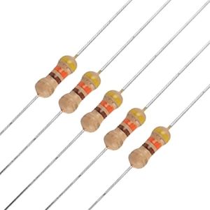
1. Fixed Resistor: A fixed resistor is a type of resistor whose resistance value remains constant during normal operation. Once it is manufactured, its resistance cannot be changed. It is one of the most commonly used passive electronic components in electrical and electronic circuits.
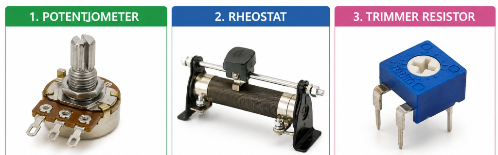
2 Variable Resistance: A variable resistor is a resistor whose resistance can be changed to increase or decrease the current flowing through an electrical circuit. Examples: Potentiometer, Rheostat, and Trimmer Resistor.
Characteristics of Resistors
- Resistors oppose the flow of electric current. This property is called resistance, and it is measured in ohms (Ω).
- The resistance of a resistor changes with temperature. It may increase or decrease depending on the material used.
- Resistors have a tolerance value. It is shown as a percentage (%) and tells how close the actual resistance is to the rated value.
- Resistors have a power rating. It is measured in watts (W) and shows the maximum power the resistor can safely handle.
- Resistors can be fixed or variable. Fixed resistors have a constant resistance, while variable resistors allow the resistance to be adjusted.
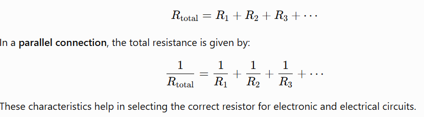
- Resistors can be connected in series, parallel, or mixed combinations. The total resistance depends on how they are connected.
- Two or more resistors can be connected in series, parallel, or a combination of both. In a series connection, the total resistance is the sum of all individual resistances:
Color Coding of Resistor
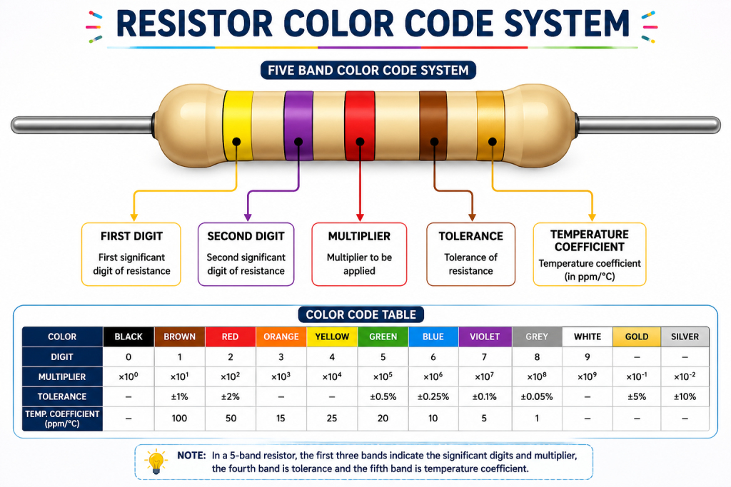
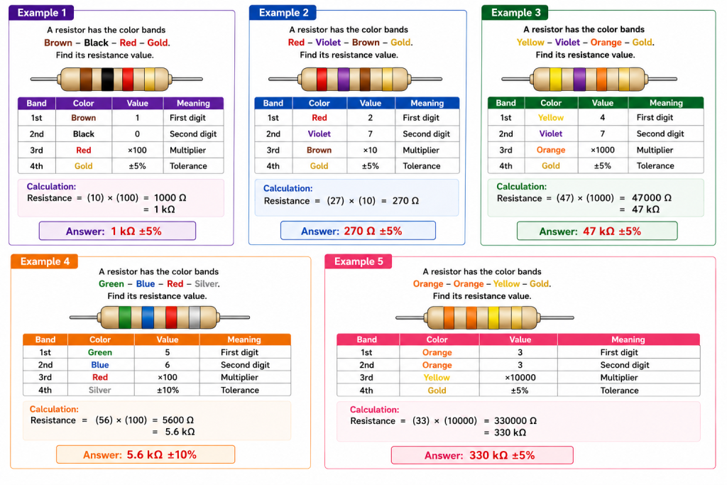
Color coding of a resistor is a method of using colored bands to show the resistance value, tolerance, and sometimes the temperature coefficient of a resistor.
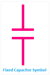
A capacitor
A capacitor is a passive electronic component that stores electrical energy in the form of an electric field between two conducting plates separated by an insulating material called a dielectric. It stores electric charge when connected to a power source and releases the stored energy when needed.
The ability of a capacitor to store charge is called capacitance. Capacitance is measured in farads (F). The value of capacitance depends on the shape and size of the conducting surfaces, their separation, and the nature of the dielectric medium used.
Classification of Capacitors
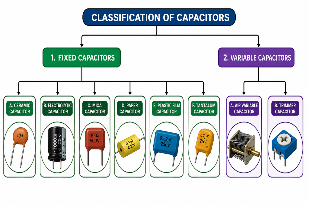
Capacitors are classified in different ways based on their construction, dielectric material, and whether their capacitance can be changed. The two main categories are fixed capacitors and variable capacitors.
1. Fixed Capacitors
A fixed capacitor has a constant capacitance value that cannot be adjusted after manufacturing. These capacitors are widely used in electronic circuits for filtering, coupling, decoupling, and energy storage.
Types of Fixed Capacitors
A) Ceramic Capacitor
A ceramic capacitor is a type of fixed capacitor that uses ceramic material as the dielectric (insulating material) between two metal plates. It is used to store electrical energy in an electric field and is widely used in electronic circuits because of its small size, low cost, high reliability, and good performance at high frequencies.
B) Electrolytic Capacitors:
An electrolytic capacitor is a type of fixed, polarized capacitor that provides a high capacitance value compared to other capacitors of the same size. It uses a thin metal oxide layer as the dielectric (insulating material) and an electrolyte as one of its conducting plates. Because of its high capacitance, it is widely used in power supplies, amplifiers, and electronic circuits for filtering, smoothing, and energy storage.
Unlike ceramic capacitors, electrolytic capacitors have polarity, meaning they must be connected correctly. The positive (+) and negative (−) terminals should never be reversed, as incorrect connection may damage the capacitor or cause it to burst.
C). Mica Capacitor
A mica capacitor is a type of fixed capacitor that uses mica as the dielectric (insulating material) between two metal plates. Mica is a natural mineral with excellent insulating properties, making these capacitors highly stable, reliable, and suitable for high-frequency and high-voltage applications. Mica capacitors are known for their long life, low energy loss, and accurate capacitance values.
D) Paper Capacitor :
A paper capacitor is a type of fixed capacitor that uses paper as the dielectric (insulating material) between two thin metal plates or metal foils. The paper is usually impregnated with wax, oil, or resin to improve its insulation, prevent moisture absorption, and increase its durability. Paper capacitors were widely used in older electronic equipment but have largely been replaced by plastic film capacitors because of their better performance and longer life.
E) plastic film capacitor
A plastic film capacitor is a type of fixed capacitor that uses a thin plastic film as the dielectric (insulating material) between two metal plates. Common plastic films used include polyester, polypropylene, polycarbonate, and polystyrene. These capacitors are known for their high reliability, low energy loss, excellent stability, and long service life. They are widely used in electronic circuits for coupling, filtering, timing, and noise suppression.
F) Tantalum Capacitor
A tantalum capacitor is a type of electrolytic capacitor that uses tantalum metal as the anode and a thin layer of tantalum oxide as the dielectric (insulating material). It provides high capacitance, excellent stability, and low leakage current in a very small size. Tantalum capacitors are widely used in modern electronic devices such as mobile phones, laptops, medical equipment, and communication systems.
Unlike ceramic capacitors, tantalum capacitors are polarized, meaning they must be connected with the correct positive (+) and negative (−) terminals.
2. Variable Capacitor
A variable capacitor allows the capacitance value to be adjusted manually or automatically. These capacitors are mainly used for tuning electronic circuits.
Types of Variable Capacitors
A )Air Variable Capacitor
An air variable capacitor is a type of variable capacitor that uses air as the dielectric (insulating material) between its plates. The capacitance can be changed by rotating a shaft that varies the overlapping area of the plates. Air variable capacitors are mainly used in radio receivers, transmitters, tuning circuits, and communication equipment because they provide accurate and smooth adjustment of capacitance.
B)Trimmer capacitors
A trimmer capacitor is a type of small variable capacitor that is used for fine adjustment (trimming) of capacitance in electronic circuits. Unlike ordinary variable capacitors, a trimmer capacitor is not adjusted frequently. It is usually set once during the manufacturing, testing, or servicing of electronic equipment to achieve accurate circuit performance.
Trimmer capacitors are commonly found in radio receivers, transmitters, oscillators, filters, and communication equipment, where precise tuning is required.
Characteristics of Capacitors
- A capacitor has two terminals and is used to store electrical charge. The ability to store charge is called capacitance.
- A capacitor with a higher capacitance can store more electrical charge than a capacitor with a lower capacitance.
- Some capacitors, such as electrolytic capacitors, are polarized and have positive (+) and negative (−) terminals. Other capacitors are non-polarized.
- Fixed and Variable Types: Capacitors are available with fixed capacitance or variable capacitance, depending on the application.
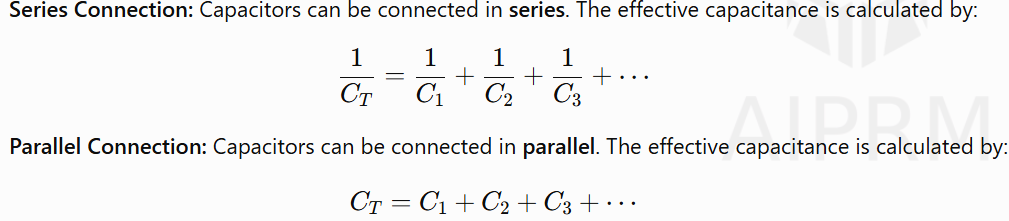
- Mixed Connection: Capacitors can also be connected in a mixed (series-parallel) combination to obtain the required capacitance.
- The capacitor has the tendency to oppose the change in the voltage across it.
- The capacitance of the capacitor is affected by the cross-sectional area of plate, the distance between the plates, and the nature of the dielectric used in the capacitor.
- Capacitors have a voltage rating, tolerance, leakage current, and temperature coefficient.
Numeric Code of Capacitors
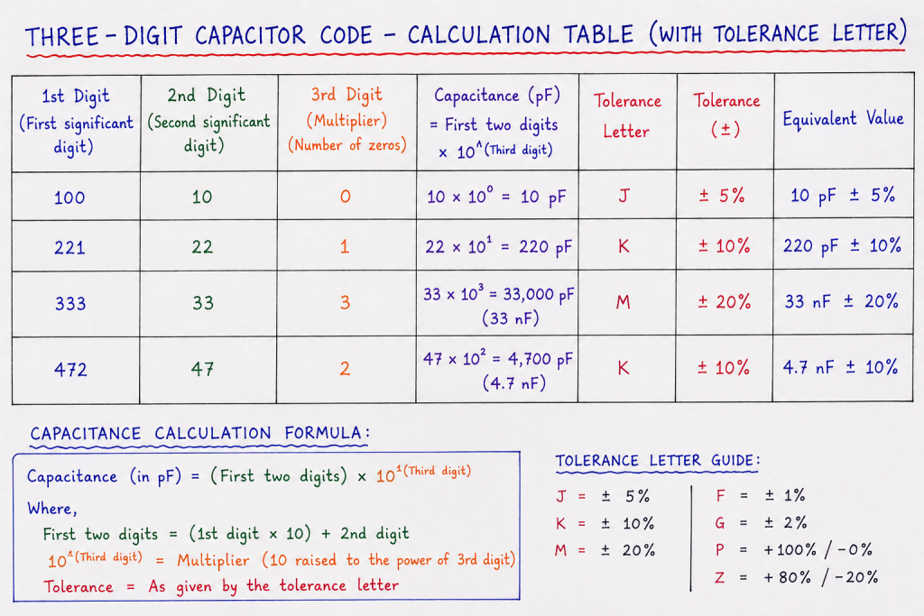
The numeric code of a capacitor is a standard method of indicating its capacitance value using numbers and letters. In the three-digit code, the first two digits represent the significant figures, and the third digit indicates the number of zeros to be added. The capacitance is expressed in picofarads (pF).
Three-Digit Capacitor Code
The three-digit capacitor code is the most commonly used method for indicating the capacitance value of ceramic and other small capacitors. In this coding system, the first digit represents the first significant number, the second digit represents the second significant number, and the third digit indicates the number of zeros (multiplier) that should be added to the first two digits. The calculated capacitance is always expressed in picofarads (pF).
The capacitance can be calculated using the following formula:
Capacitance (pF) = First Two Digits × 10^(Third Digit)
For example, if a capacitor is marked 104, the first two digits are 10, and the third digit is 4. Therefore, the capacitance is 10 × 10⁴ = 100,000 pF, which is equal to 100 nF or 0.1 µF.
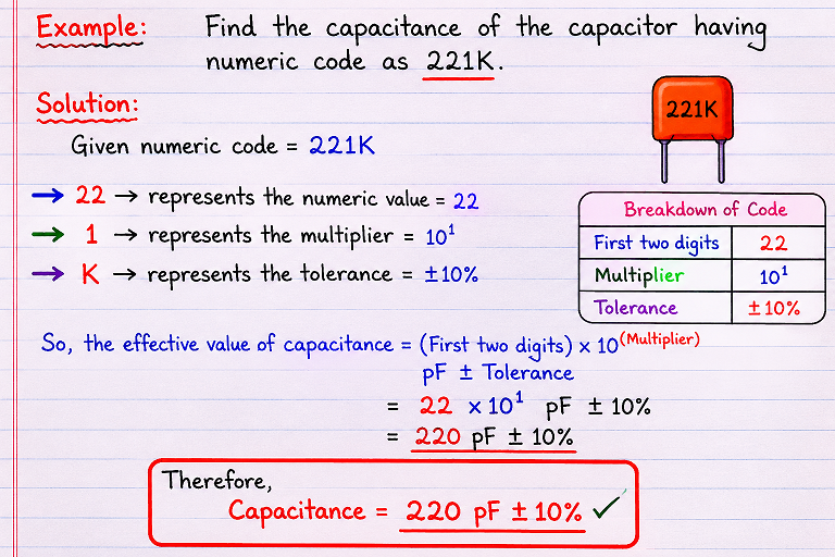
Example: Find the capacitance of the capacitor having a numeric code of 221K.
Indictors
An inductor is a passive electrical component that stores energy in the form of a magnetic field when electric current flows through it. It is usually made by winding insulated copper wire into a coil. The unit of inductance is the henry (H).
When the current through an inductor changes, it produces a voltage that opposes the change in current. This property is called inductance.
Classification of inductors
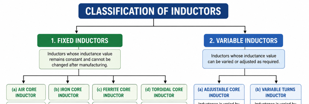
1. fixed inductor
A fixed inductor is an inductor whose inductance value remains constant and cannot be adjusted after manufacturing. Fixed inductors are the most commonly used inductors in electronic and electrical circuits. Their inductance depends on the number of turns, coil dimensions, and the type of core material.
a). Air Core Inductor:
An air core inductor is an inductor that uses air as the magnetic core instead of a magnetic material. Since air has very low magnetic permeability, the inductance is lower than other core types. When electric current flows through the coil, a magnetic field is produced around it. Since the core is air, there are no magnetic core losses.
b). Iron Core Inductor:
An iron-core inductor is a type of inductor that uses a soft iron or other ferromagnetic material as its core. The iron core strengthens the magnetic field produced by the coil, resulting in a much higher inductance than an air-core inductor. Because of its high inductance and ability to handle larger currents, it is mainly used in low-frequency and power applications.
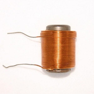
c.) Ferrite-Core Inductor
A ferrite-core inductor is a type of inductor that uses a ferrite core, which is a ceramic magnetic material with high magnetic permeability and low electrical conductivity. The ferrite core increases the inductance while minimizing eddy current losses, making it ideal for medium- and high-frequency applications. Ferrite-core inductors are widely used in modern electronic circuits because of their high efficiency and low power loss.
d) Powdered Iron Core Inductor :
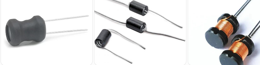
A powdered iron-core inductor is a type of inductor that uses a core made from compressed iron powder mixed with an insulating material. The insulating layer between the iron particles reduces eddy current losses while maintaining good magnetic properties. These inductors provide stable inductance, can handle high current, and perform well over a wide range of frequencies. They are commonly used in power
e) Toroidal Inductor :
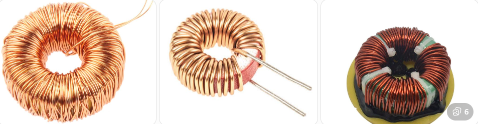
A toroidal inductor is a type of inductor in which the coil is wound around a ring-shaped (toroidal) magnetic core made of ferrite, powdered iron, or other magnetic materials. The toroidal shape confines the magnetic field within the core, reducing magnetic flux leakage and electromagnetic interference (EMI). These inductors are highly efficient and are widely used in power and electronic circuits.
2. Variable Inductors:
A variable inductor is an inductor whose inductance value can be adjusted according to the circuit’s requirements. The inductance is usually varied by moving a magnetic core (such as ferrite or iron) in and out of the coil or by changing the effective number of turns. This allows the inductor to be tuned for different frequencies and operating conditions. Variable inductors are mainly used in tuning, calibration, and frequency adjustment circuits.
a) Adjustable-Core Variable Inductor :
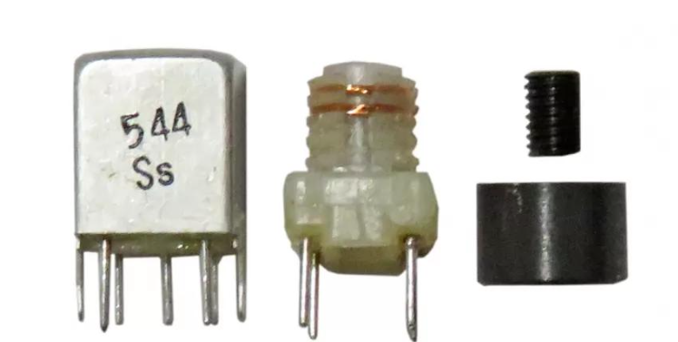
An adjustable-core variable inductor is a type of variable inductor in which the inductance is changed by moving a magnetic core (usually ferrite or soft iron) inside the coil. The core is adjusted using a screw or threaded mechanism. When the core is moved deeper into the coil, the inductance increases. When the core is moved outward, the inductance decreases. This type of inductor is widely used for tuning and calibration in electronic circuits.
b) Variable-Turns Inductor :
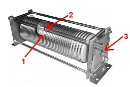
A variable-turns inductor is a type of variable inductor in which the inductance is changed by varying the effective number of turns of the coil. This is usually done using a sliding contact (roller) or by selecting different taps on the coil. Increasing the number of active turns increases the inductance, while decreasing the number of active turns reduces the inductance. These inductors are commonly used in circuits that require a wide range of inductance adjustment.
Comparison Between Fixed and Variable Inductors
| Fixed Inductor | Variable Inductor |
|---|---|
| The inductance value is fixed and cannot be changed. | The inductance value can be adjusted as required. |
| Has a simple construction with no moving parts. | Has a movable core or adjustable turns for changing inductance. |
| More reliable because there are no adjustable parts. | Slightly less reliable due to the presence of movable parts. |
| Less expensive and widely available. | More expensive than fixed inductors. |
| Easy to install and requires no adjustment after installation. | Requires manual adjustment during tuning or calibration. |
| Used in general electronic circuits where a constant inductance is needed. | Used in tuning and frequency adjustment circuits. |
| Available in air-core, iron-core, ferrite-core, powdered iron-core, and toroidal-core types. | Available as adjustable-core and variable-turns (roller) inductors. |
| Common applications include power supplies, filters, chokes, and DC–DC converters. | Common applications include radio receivers, RF circuits, antenna tuning, oscillators, and communication equipment. |
Characteristics of Inductors
- An inductor stores electrical energy in the form of a magnetic field when current flows through it.
- It opposes sudden changes in current, and this property is called inductance, which is measured in henry (H).
- An inductor is represented by the symbol L in electrical circuits.
- It offers very low resistance to DC after steady state but opposes AC through inductive reactance.
- The inductive reactance increases as the frequency or inductance increases.
- The strength of the magnetic field depends on the current flowing through the coil and the number of turns.
- The core material (air, iron, ferrite, or powdered iron) affects the inductance, efficiency, and operating frequency.
- An inductor stores energy when current increases and releases it back to the circuit when current decreases.
- Every inductor has a maximum current rating, and exceeding it may reduce performance due to core saturation.
- The coil has a small internal resistance (DC resistance), causing some power loss, while a higher Q-factor indicates better efficiency and lower energy loss.
- Inductors are widely used in filters, power supplies, oscillators, transformers, and communication circuits.
Applications of Inductors
Inductors are widely used in electrical and electronic circuits because they can store energy in a magnetic field, filter signals, and oppose changes in current. They play an important role in power systems, communication equipment, and electronic devices.
Applications
- Inductors are used in power supplies to store energy and provide a smooth and stable output current.
- : Inductors are used in electronic filters to remove unwanted noise and allow only the desired signals to pass.
- Inductors are used in transformers to transfer electrical energy from one circuit to another through magnetic induction.
- Inductors are used in motors and generators to produce the magnetic field required for their operation.
- Inductors are used in radio and communication circuits to tune and select the required frequencies.
- Inductors are used with capacitors in oscillator circuits to generate electrical oscillations.
- Inductors are used in relays, solenoids, and electromagnets to produce strong magnetic fields.
- Inductors are used in switching power supplies and converters to store and release electrical energy efficiently.
- Inductors are used in audio and communication systems to improve signal quality by reducing unwanted interference.
- Inductors are used in inductive sensors and metal detectors to detect the presence of metal objects.
Compiled By Er. Basant kumar yadav