1. Introduction to Logic Gates and Truth Tables
Logic gates are the fundamental building blocks of digital electronics. These gates process binary inputs (0s and 1s) and produce a logical output based on predefined rules. They are widely used in computing, digital circuits, and automation systems.
What is a Truth Table?
A truth table represents the input-output relationship of a logic gate. It lists all possible combinations of inputs and their corresponding outputs, providing a clear understanding of how a gate functions.
For example, here’s a simple truth table for an OR gate:
| INPUT: A | INPUT: B | OUTPUT: Y = A + B |
|---|---|---|
| 0 | 0 | 0 |
| 0 | 1 | 1 |
| 1 | 0 | 1 |
| 1 | 1 | 1 |
Now, let’s explore different types of logic gates in detail.
2. Fundamental Logic Gates
2.1 Inverter (NOT Gate)
- The NOT gate, also known as an inverter, is the simplest logic gate. It has only one input and produces an output that is the logical complement of the input.
- The symbol of the NOT gate is shown in the below diagram.
- it includes one input A , and produces out put Y= A’

- The boolean expression of NOT gate is given as Y= A̅
Truth Table for NOT Gate
| Input (A) | Output Y=(A̅) |
|---|---|
| 0 | 1 |
| 1 | 0 |
Working Principle
- If the input is
0, the output is1. - If the input is
1, the output is0.
2.2 OR Gate
- OR gate is a basic electronic gate that gives an output of 1 (true) if at least one of its inputs is 1. If both inputs are 0, the output is 0 (false).
- The OR gate produces an output of
1if at least one input is1. It follows the Boolean equation:
- The symbol of the OR gate is shown in the below diagram.

Truth Table for OR Gate
| INPUT: A | INPUT: B | OUTPUT: Y = A + B |
|---|---|---|
| 0 | 0 | 0 |
| 0 | 1 | 1 |
| 1 | 0 | 1 |
| 1 | 1 | 1 |
2.3 AND Gate
- The AND gate produces an output of
1only if both inputs are1. Its Boolean expression is:
Y=A⋅B
- The symbol of the AND gate and its truth table are explained below.

Truth Table for AND Gate
| INPUT: A | INPUT: B | OUTPUT: Y = A.B |
|---|---|---|
| 0 | 0 | 0 |
| 0 | 1 | 0 |
| 1 | 0 | 0 |
| 1 | 1 | 1 |
2.4 NOR Gate
- The NOR gate is the combination of an OR gate followed by a NOT gate.
- It produces an output of
1only when all inputs are0. - The symbol of the NOR gate is shown below the diagram, it includes two inputs input A and input B, and produces out put Y= (A+B)’

Truth Table for NOR Gate
| INPUT: A | INPUT: B | OUTPUT: Y = (A+B)’ |
|---|---|---|
| 0 | 0 | 1 |
| 0 | 1 | 0 |
| 1 | 0 | 0 |
| 1 | 1 | 0 |
2.5 NAND Gate
- The NAND gate is an AND gate followed by a NOT gate. It produces an output of
0only when both inputs are1. - The symbol of the NAND gate is shown below the diagram.
- it includes two inputs input A, and input B, and produces output Y= (A.B)’
- The boolean expression of the NAND gate is given as
Y= (AB)’

Truth Table for NAND Gate
| INPUT: A | INPUT: B | OUTPUT: Y = (A.B)’ |
|---|---|---|
| 0 | 0 | 1 |
| 0 | 1 | 1 |
| 1 | 0 | 1 |
| 1 | 1 | 0 |
2.6 Universal Gates
- NAND and NOR gates are called universal gates because they can implement any Boolean function.
- These universal gates play a crucial role in circuit design and optimization.
Special Purpose Gate:
- Exclusive OR (Ex-OR)and Exclusive NOR (X-NOR) gates are called special-purpose gates due to their unique behavior and specific use cases in digital circuits. Unlike basic gates such as AND, OR, or NOT, which are used for general-purpose logic operations, the XOR gate has specialized applications that make it particularly useful in certain scenarios. Let’s break down why it’s called a special-purpose gate.
3.1 EX-OR Gate
- An Exclusive OR (XOR) gate, also known as an E-OR gate, is a digital logic gate that outputs true (or 1) only when the inputs to it are different.
- If both inputs are the same (either both 0 or both 1), the output is false (or 0).
- The symbol of the Ex-OR gate is shown in the below diagram.

| INPUT: A | INPUT: B | OUTPUT: Y = A ⊕ B. |
|---|---|---|
| 0 | 0 | 0 |
| 0 | 1 | 1 |
| 1 | 0 | 1 |
| 1 | 1 | 0 |
3.2 EX-NOR Gate
- An Ex-NOR gate, also known as the Exclusive NOR gate or XNOR gate, is a type of digital logic gate that is the complement (inversion) of the Exclusive OR (XOR) gate.
- It produces a high output (1) only when the number of true inputs is even. In simpler terms, it outputs 1 if both inputs are the same, and 0 if the inputs are different.
- The symbol of EX-NOR gate is shown in the below diagram.
- The boolean expression of the E-NOR gate is given as
Y = A ⊙ B = (A AND B) OR (NOT A AND NOT B)

| INPUT: A | INPUT: B | OUTPUT: Y = A ⊙ B |
|---|---|---|
| 0 | 0 | 1 |
| 0 | 1 | 0 |
| 1 | 0 | 0 |
| 1 | 1 | 1 |
Demorgon theorem:
DeMorgan’s Theorem is a powerful theorem in Boolean algebra that has a set of two rules or laws. These two laws were developed to show the relationship between the two variables AND, OR, and NOT operations.
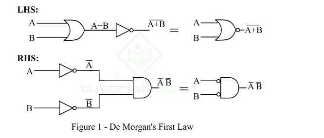
Demorgon’s first theorem:
DeMorgan’s First Law states that the complement of a sum (ORing) of variables is equal to the product (ANDing) of their complements. In other words, the complement of two or more ORed variables is equivalent to the AND of the complements of each of the individual variables, i.e.,
(A+B)′=A′⋅B′
- Logic diagram implementations of demorgon first law
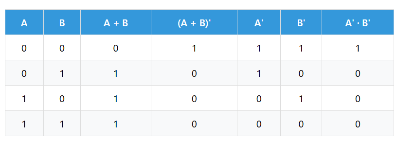
 Truth table of demorgon first law
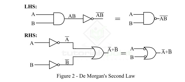
Demorgon’s second theorem:
- DeMorgan’s second law states that the complement of the product of variables is equivalent to the sum of their individual complements.
- In other words, DeMorgan’s second law states that the complement of the product (ANDing) of variables is equivalent to the sum (ORing) of their individual complements. i.e.
(AB)‘ = A‘ +B‘
- The logical implementation of both the left and right sides of this expression is shown diagram below.
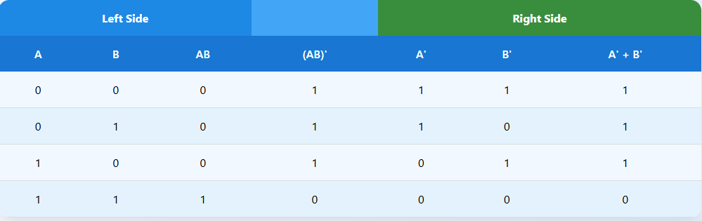
Truth table of demorgon second law.
NAND Gate As A Universal Gate:
The NAND gate is called a Universal Gate because it can be used to create all other basic logic gates—such as NOT, AND, and OR—and any digital circuit. This means that any logic circuit can be built using only NAND gates.
Implementation of the AND Gate Using Only NAND Gates
NAND gate is a type of universal logic gate, because it can be used to implement any other logic gate. The implementation of an AND gate using a NAND gate is shown in the diagram below.

From the circuit diagram, it is clear that implementing an AND gate using NAND gates is quite simple, as it only requires two NAND gates.
The first NAND gate gives the complement (NOT) of the binary product of inputs A and B. The second NAND gate then inverts this output again, producing the final AND output. Therefore, the logic circuit using NAND gates, as shown in the above diagram, works exactly like a standard AND gate.