
Introduction ofOSI model and TCP/IP Model
Computer networks allow devices around the world to communicate, exchange information, and access online services. However, successful communication between computers requires a set of rules, standards, and protocols.
Two important networking models that explain how network communication works are the OSI Model (Open Systems Interconnection Model) and the TCP/IP Model (Transmission Control Protocol/Internet Protocol Model).
Both models describe how data travels from one device to another through a network. The OSI model divides network communication into seven layers, whereas the commonly used TCP/IP model organizes communication into four layers.
Understanding these models is essential for students, network administrators, IT professionals, and anyone preparing for networking certifications such as CompTIA Network+ and Cisco CCNA.
In this article, you will learn about the OSI model, TCP/IP model, their layers, functions, protocols, major differences, practical examples, and networking interview questions.
1. What Is the OSI Model?
The OSI (Open Systems Interconnection) Model is a conceptual networking framework developed by the International Organization for Standardization (ISO). It explains how data is transmitted between computers through a network.
The OSI model divides network communication into seven separate layers. Each layer performs a specific function and communicates with the layers directly above and below it.
The seven layers of the OSI model are:
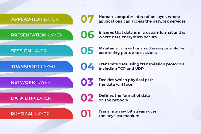
Physical Layer
Data Link Layer
Network Layer
Transport Layer
Session Layer
Presentation Layer
Application Layer
Seven Layers of the OSI Model
| Layer | Name | Main Function | Examples |
|---|---|---|---|
| 7 | Application | Provides network services to applications | HTTP, FTP, DNS, SMTP |
| 6 | Presentation | Data formatting, encryption and compression | TLS, JPEG, ASCII |
| 5 | Session | Establishes and manages communication sessions | Session management |
| 4 | Transport | End-to-end data delivery and reliability | TCP, UDP |
| 3 | Network | Logical addressing and routing | IP, ICMP |
| 2 | Data Link | Framing and local network delivery | Ethernet, Wi-Fi, MAC |
| 1 | Physical | Transmits raw bits through physical media | Cables, radio signals, hubs |
1.1 Physical Layer
The Physical Layer is the first and lowest layer of the OSI model. It is responsible for transmitting raw bits (0s and 1s) through physical transmission media.It defines the electrical, mechanical, and physical characteristics required for data transmission.
Main functions:
- Transmits raw bits over communication media.
- Defines cables, connectors, and transmission frequencies.
- Specifies data transmission rates.
- Defines electrical and optical signals.
- Establishes physical connections between devices.
Examples: Ethernet cables, fiber-optic cables, radio signals, hubs, and repeaters.
1.2 Data Link Layer
The Data Link Layer is the second layer of the OSI model. It provides node-to-node data delivery over a local network.It converts data into frames and uses MAC addresses to identify devices on a local network.
Main functions:
- Converts network packets into frames.
- Provides physical addressing using MAC addresses.
- Detects transmission errors.
- Controls access to shared transmission media.
- Manages communication between directly connected devices.
Examples: Ethernet, Wi-Fi (IEEE 802.11), switches, and MAC addressing.
1.3 Network Layer
The Network Layer is the third layer of the OSI model. It is responsible for logical addressing and routing data packets between different networks.It determines the appropriate path through which data should travel to reach its destination.
Main functions:
- Provides logical addressing using IP addresses.
- Determines routes between networks.
- Forwards packets toward their destinations.
- Supports communication across interconnected networks.
- Handles packet fragmentation where applicable.
Examples: IPv4, IPv6, IP routers, and ICMP.
1.4 Transport Layer
The Transport Layer is the fourth layer of the OSI model. It provides end-to-end communication between applications running on different devices.It divides data into smaller segments and supports reliable or connectionless data delivery.
Two important transport protocols are:
TCP (Transmission Control Protocol):
- Provides reliable data transmission.
- Establishes connections before communication.
- Uses acknowledgments and retransmissions.
- Maintains the correct order of data.
Provides flow control and congestion control.
UDP (User Datagram Protocol):
- Provides connectionless communication.
- Has lower protocol overhead.
- Does not guarantee delivery or ordering.
- Is useful for real-time applications.
Examples: TCP, UDP, and port numbers.
1.5 Session Layer
The Session Layer is the fifth layer of the OSI model. It establishes, manages, and terminates communication sessions between applications.
Main functions:
- Establishes communication sessions.
- Maintains active sessions.
- Coordinates data exchange.
- Terminates communication sessions.
- Supports synchronization and recovery points in suitable communication systems.
Example: Managing an ongoing communication session between two applications.
1.6 Presentation Layer
The Presentation Layer is the sixth layer of the OSI model. It is responsible for presenting data in a format that the receiving application can understand. It handles data translation, encryption, decryption, and compression.
Main functions:
- Converts data into suitable formats.
- Supports data encryption and decryption.
- Performs data compression and decompression.
- Helps ensure compatible data representation.
Examples: JPEG, PNG, ASCII, Unicode, and data encoding formats.
1.7 Application Layer
The Application Layer is the seventh and highest layer of the OSI model. It provides network-related services to user applications.
It acts as an interface between network services and application software.
Main functions:
- Provides access to network services.
- Supports web browsing and email communication.
- Enables file transfer.
- Supports name resolution and network management.
Examples: HTTP, HTTPS, FTP, SMTP, DNS, and SSH.
2. What Is the TCP/IP Model?
The TCP/IP Model (Transmission Control Protocol/Internet Protocol Model) is a networking framework that describes how devices communicate over interconnected networks, including the Internet. It is based on the TCP/IP protocol suite, which originated from research supported by the United States Department of Defense through DARPA.
Unlike the seven-layer OSI model, the commonly taught TCP/IP model consists of four layers.
The four layers are:
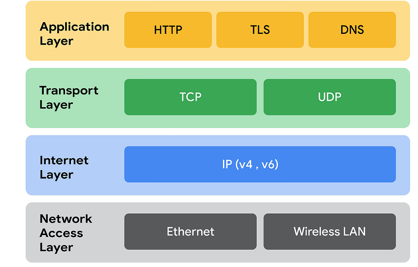
- Network Access Layer
- Internet Layer
- Transport Layer
- Application Layer
Four Layers of the TCP/IP Model
| Layer | Main Function | Examples |
|---|---|---|
| Application | Provides network services to applications | HTTP, HTTPS, FTP, DNS, SMTP |
| Transport | Provides end-to-end communication | TCP, UDP |
| Internet | Handles logical addressing and routing | IPv4, IPv6, ICMP |
| Network Access | Handles local network communication and physical transmission | Ethernet, Wi-Fi |
2.1 Network Access Layer
The Network Access Layer is the lowest layer of the TCP/IP model. It handles communication between devices connected to the same local network.It combines functions associated with the Physical and Data Link Layers of the OSI model.
Main functions:
- Transmits data through network media.
- Converts data into frames.
- Uses MAC addresses for local delivery.
- Handles access to the transmission medium.
- Supports communication through wired and wireless networks.
Examples: Ethernet, Wi-Fi, network cables, and network interface cards.
2.2 Internet Layer
The Internet Layer is responsible for delivering packets from the source network to the destination network.It uses logical IP addresses and routing mechanisms to transfer packets across interconnected networks.
Main functions:
- Provides logical IP addressing.
- Routes packets between networks.
- Forwards packets toward their destinations.
- Supports communication across the Internet.
- Handles packet fragmentation in applicable protocols.
Examples: IPv4, IPv6, and ICMP.
2.3 Transport Layer
The Transport Layer provides communication between applications running on different devices. It uses port numbers to identify applications and supports different methods of data delivery.
The two major transport protocols are TCP and UDP.
Main functions:
- Provides end-to-end communication.
- Divides application data into smaller units.
- Supports reliable data transmission through TCP.
- Supports connectionless transmission through UDP.
- Provides port-based application identification.
Examples: TCP and UDP.
2.4 Application Layer
The Application Layer is the highest layer of the TCP/IP model. It provides network communication services to applications. Unlike the OSI model, it combines the responsibilities of the Application, Presentation, and Session Layers.
Main functions:
- Provides application-level network services.
- Supports web communication.
- Enables email and file transfer.
- Handles domain name resolution.
- Supports application data formatting and communication.
Examples: HTTP, HTTPS, FTP, DNS, SMTP, SSH, and DHCP.
3. OSI Model vs TCP/IP Model: 7 Key Differences
The OSI and TCP/IP models explain network communication using different numbers of layers and different architectural approaches. The OSI model is mainly a reference framework for understanding networking functions, while TCP/IP describes the protocol architecture used for Internet communication.
Comparison Between OSI and TCP/IP Models
| Basis | OSI Model | TCP/IP Model |
|---|---|---|
| Full form | Open Systems Interconnection | Transmission Control Protocol/Internet Protocol |
| Number of layers | 7 layers | 4 layers in the common model |
| Development | ISO | DARPA research lineage |
| Architecture | Reference model | Protocol architecture |
| Application functions | Application, Presentation and Session are separate | Combined in Application Layer |
| Network access functions | Physical and Data Link are separate | Combined in Network Access Layer |
| Transport protocols | Supports different transport protocols | Primarily TCP and UDP in the Internet protocol suite |
| Layer separation | More detailed separation of functions | More practical grouping of functions |
| Main purpose | Understanding and describing network communication | Implementing communication across interconnected networks |
| Practical use | Education, network design and troubleshooting | Internet and network communication |
Mapping of OSI Layers to TCP/IP Layers
The following table explains how the seven OSI layers correspond to the four commonly taught TCP/IP layers.
| OSI Model (7 Layers) | TCP/IP Model (4 Layers) |
|---|---|
| Application | Application |
| Presentation | Application |
| Session | Application |
| Transport | Transport |
| Network | Internet |
| Data Link | Network Access |
| Physical | Network Access |
Important: The TCP/IP Network Access Layer is sometimes divided into Data Link and Physical Layers in a five-layer teaching model. Both approaches describe the same general networking functions at different levels of detail.
4. How Data Travels Through the OSI and TCP/IP Models
Understanding how data moves through networking layers makes it easier to understand both models.
Consider a simple example: You open a web browser and visit a website such as Google.
The following steps explain how communication takes place.
Step 1: Application Layer
You enter a website address into your browser. The browser prepares an HTTP or HTTPS request to communicate with the web server.
Step 2: Transport Layer
The transport layer uses TCP to establish reliable communication when TCP is used. It divides application data into smaller segments and adds transport information, including port numbers.
Step 3: Internet Layer
The Internet Layer adds source and destination IP addresses to packets. Routers use IP information to forward packets toward the destination.
Step 4: Network Access Layer
The network access layer prepares frames for transmission over Ethernet or Wi-Fi. The data is converted into signals and transmitted through the network medium.
Step 5: Receiving Device
The receiving device processes the data through the corresponding networking layers. Each layer interprets and removes its relevant protocol information.
Step 6: Application Receives Data
Finally, the receiving application processes the request and generates a response.
The response travels back through the network to your browser.
This entire process happens very quickly, allowing users to access websites and online services.
5. Encapsulation and Decapsulation in Networking
Encapsulation and decapsulation are important concepts in both OSI and TCP/IP networking.
Encapsulation
Encapsulation is the process of adding protocol information to data as it moves from higher layers to lower layers before transmission.
For example:
- Application Layer: Data
- Transport Layer: Segment (TCP) or Datagram (UDP)
- Internet Layer: Packet
- Network Access Layer: Frame and physical transmission bits
Decapsulation
Decapsulation is the reverse process. When data reaches the destination device, each networking layer processes and removes its corresponding protocol information. The application finally receives the original data.
Why is encapsulation important?
- Organizes network communication.
- Supports communication between different devices.
- Provides addressing and delivery information.
- Helps networking protocols work together.
- Supports reliable and organized data transmission.
6. Real-World Applications of the OSI and TCP/IP Models
Both networking models are useful in understanding, designing, and troubleshooting computer networks.
Applications of the OSI Model
- Network Troubleshooting: Helps identify problems at different networking layers.
- Network Education: Makes networking concepts easier to understand.
- Network Design: Provides a structured way to describe networking functions.
- Protocol Development: Helps explain how different networking protocols interact.
- Technical Documentation: Provides a common language for discussing network operations.
Applications of the TCP/IP Model
- Internet Communication: Supports communication between devices across the Internet.
- Web Browsing: Enables browsers and web servers to exchange information.
- Email Communication: Supports email protocols such as SMTP and IMAP.
- File Transfer: Supports network file transfer using protocols such as FTP.
- Cloud Computing: Provides the networking foundation for cloud-based services.
- Remote Access: Supports remote communication through protocols such as SSH.
7. OSI Model and TCP/IP Model in Network Troubleshooting
The OSI model is particularly useful for identifying network problems systematically.
Here are some practical examples:
| Problem | Relevant OSI Layer | Possible Cause |
|---|---|---|
| No network connection | Physical | Damaged cable or disconnected device |
| Local network communication failure | Data Link | MAC address or switching issue |
| Cannot reach a remote IP address | Network | Routing or IP configuration problem |
| Application connection fails | Transport | TCP connection or port issue |
| Website name cannot be resolved | Application | DNS configuration problem |
| Website displays incorrectly | Application / Presentation concepts | Application or data-format issue |
Example: Troubleshooting a Website Connection
Suppose a user cannot access a website.
A network administrator may:
- Check the network cable or Wi-Fi connection.
- Check the IP address and default gateway.
- Test connectivity using
ping. - Check DNS resolution using
nslookup. - Test whether the required TCP port is accessible.
- Check browser and server-related issues.
This layered approach helps isolate problems instead of randomly changing network settings.
8. Which Model Is Better: OSI or TCP/IP?
There is no universal winner because both models serve different purposes.
OSI Model:
- Provides a detailed seven-layer reference framework.
- Helps students understand networking concepts.
- Makes troubleshooting easier to organize.
- Separates networking functions into clearly defined layers.
- TCP/IP Model:
- Describes the architecture used for Internet communication.
- Represents the TCP/IP protocol suite.
- Supports practical communication across interconnected networks.
- Provides the foundation for modern Internet services.
Conclusion: The OSI model is especially useful for learning and understanding network functions, whereas TCP/IP is essential for understanding how real-world Internet communication works. Both models are important for networking students and IT professionals.
9. Frequently Asked Questions (FAQs)
1. What is the main difference between the OSI and TCP/IP models?
The OSI model has seven layers, whereas the commonly taught TCP/IP model has four layers. OSI is a conceptual reference framework, while TCP/IP describes the protocol architecture used for Internet communication.
2. Why does the OSI model have seven layers?
The OSI model divides network communication into seven layers to organize different networking functions, making communication easier to understand, design, and troubleshoot.
3. Why does TCP/IP have four layers?
The TCP/IP model groups certain networking functions together. For example, the Application Layer combines functions associated with the Application, Presentation, and Session Layers of the OSI model.
4. Which model is used on the Internet?
The TCP/IP protocol suite is used for Internet communication. The OSI model is commonly used as a reference framework for understanding networking concepts.
5. What are the seven layers of the OSI model?
The seven layers are Physical, Data Link, Network, Transport, Session, Presentation, and Application.
6. What are the four layers of the TCP/IP model?
The four layers are Network Access, Internet, Transport, and Application.
7. What is the difference between TCP and UDP?
TCP provides reliable, connection-oriented data delivery, while UDP provides connectionless communication without guaranteeing delivery or ordering.
8. Which OSI layer is responsible for IP addressing?
The Network Layer (Layer 3) is responsible for logical addressing and routing using IP.
9. Which OSI layer is responsible for MAC addresses?
The Data Link Layer (Layer 2) uses MAC addresses for local network communication.
10. Which model is better for CCNA and CompTIA Network+ preparation?
Both models are important. The OSI model helps organize networking concepts and troubleshooting, while TCP/IP helps explain practical protocols and Internet communication.
10. Networking Interview Questions and Answers
Q1. What does OSI stand for?
OSI stands for Open Systems Interconnection.
Q2. What does TCP/IP stand for?
TCP/IP stands for Transmission Control Protocol/Internet Protocol.
Q3. How many layers are present in the OSI model?
There are seven layers.
Q4. How many layers are present in the commonly taught TCP/IP model?
There are four layers.
Q5. Which layer is responsible for routing?
The Network Layer in the OSI model and the Internet Layer in the TCP/IP model.
Q6. Which layer provides reliable data transmission?
The Transport Layer, particularly when TCP is used.
Q7. Which protocol is used for secure web communication?
HTTPS is used for secure web communication.
Q8. What is the PDU of the Network Layer?
The Protocol Data Unit (PDU) at the Network Layer is called a packet.
Q9. Which protocol translates domain names into IP addresses?
DNS (Domain Name System).
Q10. What is the difference between encapsulation and decapsulation?
Encapsulation adds protocol information before data transmission, whereas decapsulation processes and removes that information at the receiving device.
Conclusion
The OSI and TCP/IP models are fundamental concepts in computer networking. Both explain how data travels between devices and how different networking functions work together.
The OSI model provides a detailed seven-layer framework for understanding network communication, while the TCP/IP model describes the four-layer architecture commonly used to explain Internet communication.
Understanding these models helps students, networking beginners, network administrators, and IT professionals develop a strong foundation in computer networking, network troubleshooting, and communication protocols.
Whether you are preparing for an academic examination, CompTIA Network+, Cisco CCNA, or a networking interview, learning both models is essential.
Related Computer Networking Articles
Explore these related guides to improve your networking knowledge:
About the Author
Er. Basant Kumar Yadav is an Electronics and Communication Engineering graduate, educator, and technology blogger from Nepal. He teaches computer engineering and technology-related subjects and creates educational resources to make technical concepts easier to understand.
Through BasantYadav.com.np, he shares computer engineering notes, programming tutorials, networking guides, and educational resources for students and technology enthusiasts.
Website: https://basantyadav.com.np/
Open System Interconnection OSI Model
The OSI, or Open System Interconnection model, was developed by the International Standards Organization (ISO). It helps different communication systems talk to each other using standard protocols. The OSI model provides a layered framework that shows how communication should happen between different systems. Simply put, it sets a standard for computers to communicate with one another.
The model divides data flow in a communication system into seven layers. These layers work together to manage communication step by step. The seven layers of the OSI model are:

Each layer has a specific role in ensuring smooth communication, as shown in the diagram below.
The Seven Layers of the OSI Model
1. Physical Layer
The Physical Layer is the lowest layer of the OSI Model. It is responsible for the actual transmission of raw data bits (0s and 1s) over a physical medium. This layer defines hardware elements such as cables, switches, connectors, voltage levels, signal types, data rates, and transmission modes (simplex, half-duplex, full-duplex). It does not understand data or addresses; it only focuses on sending and receiving electrical, optical, or radio signals. Examples: Ethernet cables, fiber-optic cables, hubs, repeaters.
2. Data Link Layer
The Data Link Layer ensures reliable data transfer between two directly connected devices. It organizes raw bits from the Physical Layer into frames and detects and corrects errors that may occur during transmission. This layer also controls how devices access the shared transmission medium. It uses MAC (Media Access Control) addresses to identify devices on the same network.
This layer is divided into two sublayers:
- LLC (Logical Link Control) – manages error control and flow control.
- MAC (Media Access Control) – handles physical addressing.
Examples: Switches, Ethernet, Wi-Fi (IEEE 802 standards).
3. Network Layer
The Network Layer is responsible for routing data from the source device to the destination device across different networks.It determines the best path for data transmission and handles logical addressing using IP addresses. If data packets are too large, this layer may break them into smaller packets and reassemble them at the destination. Examples: Routers, IP (Internet Protocol), ICMP.
4. Transport Layer
The Transport Layer ensures complete, reliable, and orderly delivery of data from sender to receiver. It manages flow control, error control, and segmentation of data. Data received from upper layers is divided into smaller units called segments, and each segment is assigned a sequence number.
There are two main transport protocols:
- TCP (Transmission Control Protocol) – reliable, connection-oriented.
- UDP (User Datagram Protocol) – fast, connectionless, but less reliable.
Examples: TCP, UDP.
5. Session Layer
The Session Layer manages communication sessions between applications on different devices. It establishes, maintains, and terminates connections (sessions). This layer also handles synchronization, allowing data transfer to resume from a specific point if the connection is interrupted.
Examples: Session checkpoints, login sessions, video calls.
6. Presentation Layer
The Presentation Layer acts as a translator between the Application Layer and the network.
It converts data into a format that the receiving system can understand. This layer also handles encryption, decryption, and data compression, ensuring data security and efficiency.
Examples: SSL/TLS encryption, JPEG, MP3, video formats.
7. Application Layer
The Application Layer is the topmost layer and is closest to the user. It provides network services directly to user applications. This layer does not represent the application itself but provides networking support for applications like browsers, email clients, and file transfer programs.
Examples: HTTP (web), FTP (file transfer), SMTP (email), DNS.
Transmission Control Protocol/Internet Protocol (TCP/IP) model
The Transmission Control Protocol/Internet Protocol (TCP/IP) model is a simplified version of the OSI Model. It explains how data is sent and received over a network. The TCP/IP protocol suite was developed before the OSI Model. Its layers were designed for practical use on real networks. The layers of the TCP/IP model do not exactly match the layers of the OSI Model. Some OSI layers are combined into a single layer in TCP/IP. Because of this, TCP/IP is simpler and more widely used in the real world.
TCP/IP Protocol
- The original TCP/IP protocol model uses four layers: Host-to-Network, Internet, Transport, and Application.
- The Host-to-Network layer in the TCP/IP model is equal to the combination of the Physical layer and Data Link layer of the OSI model. It deals with hardware, network interfaces, and data transmission.
- The Internet layer of TCP/IP is similar to the Network layer of the OSI model. It is responsible for logical addressing and routing of data packets between networks.
- In the TCP/IP model, the Application layer performs the functions of the Session, Presentation, and Application layers of the OSI model. It provides services directly to user applications.
- In TCP/IP, the lower layers handle physical standards, network access, internetworking, and data transport. These layers work together to ensure smooth communication between devices.
- The top three layers of the OSI model (Application, Presentation, and Session) are combined into a single Application layer in the TCP/IP model.

Layers of the TCP/IP Model
1. Application Layer
The Application layer provides network services to application software. It allows programs on a computer to communicate with the network. This layer uses protocols such as HTTP, POP3, and SMTP. It acts as an interface between the user’s software and the network.
2. Transport Layer
The Transport layer is responsible for end-to-end data delivery. It includes Transmission Control Protocol (TCP) and User Datagram Protocol (UDP). TCP provides reliable data transfer to applications. UDP provides faster data transfer without reliability checks.
3. Internet Layer (Network Layer)
The Internet layer is similar to the Network layer (Layer 3) of the OSI model. It stores IP addresses and routing information. This layer is used when data is sent between different networks. Protocols used in this layer include IPv4, IPv6, ICMP, and routing protocols.
4. Host-to-Network (Link) Layer
The Host-to-Network layer is also called the Link layer or Network Interface layer. It handles the physical transmission of data over the network. It sends IP packets to the next router or host using hardware details. This layer is the lowest layer of the TCP/IP model. It is a combination of the Physical layer and Data Link layer of the OSI model.
Comparison Between the OSI Model and the TCP/IP Model
| OSI Model | TCP/IP Model |
|---|---|
| Open Systems Interconnection | Transmission Control Protocol / Internet Protocol |
| Developed by the International Standards Organization (ISO) | Developed by the U.S. Department of Defense (DARPA) |
| Has 7 layers | Has 4 layers |
| Conceptual and theoretical model | Practical and implementation-based model |
| Developed in 1984 | Developed in the 1970s |
| Used mainly for learning and reference | Used in real networks and the Internet |
| Physical, Data Link, Network, Transport, Session, Presentation, Application | Host-to-Network, Internet, Transport, Application |
| Session and Presentation are separate layers | Session and Presentation are part of the Application layer |
| Does not define specific protocols | Defines TCP, UDP, and SCTP |
| General framework without protocol details | Uses IP, ICMP, and ARP |
| Less flexible | More flexible |
Introduction to Protocols
In computer networks, a protocol is a set of rules that allows two or more devices to communicate with each other. Protocols define how data is sent, received, and interpreted across a network. Without protocols, computers and other devices would not understand each other, and communication would fail.
Types of Network Protocols in a Computer Network
A network protocol is a set of rules that allows computers and devices to communicate and exchange information through a network. Different protocols perform different functions depending on the type of communication
1. Communication Protocol
Communication protocols are responsible for sending and receiving data between devices connected to a network. They define how information is formatted, transmitted, and received. These protocols ensure that devices understand each other and communication happens correctly. Communication protocols play an important role in web browsing, email services, and online communication. They also help detect errors and maintain reliable data transfer.
Examples: HTTP, HTTPS, TCP, UDP, SMTP
2. Security Protocol
Security protocols are designed to protect data and communication over a network. They provide security features such as encryption, authentication, and data integrity. Encryption converts readable data into coded form so unauthorized users cannot access it. Authentication verifies the identity of users and devices before allowing access. These protocols are widely used in online banking, secure websites, and remote system access.
Examples: HTTPS, SSH, SSL/TLS
3. Network Management Protocol
Network management protocols are used to monitor, control, and manage network devices and resources. They help network administrators check network performance, detect faults, and configure devices. These protocols support smooth network operation by collecting information and managing network traffic. They are commonly used in organizations and large computer networks.
Examples: SNMP, DHCP
4. File Transfer Protocol
File transfer protocols are used to transfer files from one computer to another through a network. These protocols support uploading, downloading, storing, and sharing files. They ensure files are transferred properly and completely. File transfer protocols are commonly used in website hosting, cloud storage, and server management.
Examples: FTP, SFTP
5. Routing Protocol
Routing protocols determine the best path for transmitting data from the source device to the destination device. They help routers exchange information and choose efficient routes. These protocols improve network performance by reducing delays and managing traffic. Routing protocols are mainly used in large networks and the internet.
Examples: RIP, OSPF, BGP
IP Address (Internet Protocol Address)
An IP Address (Internet Protocol Address) is a unique numerical address assigned to each device connected to a computer network. It helps identify devices and allows them to communicate with each other over the internet or a local network.
Just like a house address helps identify a house, an IP address helps identify a computer, mobile phone, printer, or any network device.
The main purpose of an IP address is to send and receive data correctly between devices. Every device connected to a network must have an IP address.
Example of IP Address:
- IPv4: 192.168.1.1
- IPv6: 2001:0db8:85a3:0000:0000:8a2e:0370:7334
Version of IP Address
1. IPv4 (Internet Protocol Version 4)
IPv4 is the older and most commonly used version of IP addressing. It uses 32 bits and consists of four groups of numbers separated by dots. Each group ranges from 0 to 255. IPv4 supports a limited number of addresses. Example: 192.168.1.1
Structure of IPv4
IPv4 uses a 32-bit address divided into four parts called octets. Each octet contains 8 bits and is separated by dots (.). The value of each octet ranges from 0 to 255. Each IPv4 address is written in Decimal form (human-readable) and Binary form (computer-readable) Example:
Decimal Format: 192.168.1.10 ,Binary Format: 11000000.10101000.00000001.00001010
Features of IPv4
- IPv4 uses a total of 32 bits to create addresses. This allows approximately 4.3 billion unique IP addresses.
- IPv4 addresses use a simple decimal format separated by dots, making them easy to read and use.
- It enables devices to communicate and exchange information through networks.
- IPv4 is still the most commonly used internet addressing system.
- IPv4 is still the most commonly used internet addressing system.
2. IPv6 (Internet Protocol Version 4)
IPv6 (Internet Protocol version 6) is the newest version of the Internet Protocol used to identify devices on a network and enable communication over the internet. It was developed by the Internet Engineering Task Force (IETF) to replace IPv4 because the number of available IPv4 addresses was running out.
Structure of Internet Protocol version 6 (IPv6)
IPv6 is a 128-bit internet addressing system designed to replace IPv4 and support the growing number of devices connected to the internet. Its structure is simple but highly powerful and organized for modern networking needs.
The IPv6 address is divided into eight equal parts called blocks or hextets. Each block contains 16 bits and is written in hexadecimal format using numbers from 0 to 9 and letters from A to F. These blocks are separated by colons (:). For example, a full IPv6 address looks like this:
2001: 0db8: 85a3: 0000: 0000: 8a2e: 0370: 7334.
To make it easier to read and write, IPv6 allows simplification by removing leading zeros and replacing consecutive zero blocks with a double colon (::), such as 2001:db8:85a3::8a2e:370:7334.
Features of IPv6
- IPv6 uses 128-bit addresses, allowing a very large number of unique IP addresses.
- It provides a larger address space than IPv4, supporting billions of connected devices.
- The header format is simplified, which improves routing efficiency and packet processing speed.
- IPv6 supports automatic address configuration, reducing the need for manual network setup.
- It includes built-in security features through IPsec for authentication and data encryption.
- IPv6 supports multicast communication, sending data to multiple devices efficiently.
- It eliminates the need for Network Address Translation (NAT), enabling direct device-to-device communication.
- Quality of Service (QoS) support helps prioritize important traffic such as voice and video.
- It offers better mobility support, allowing devices to maintain connections while moving between networks.
- IPv6 provides more efficient routing, reducing network congestion and improving performance.
Comparison between ipv4 and ipv6
| IPv4 | IPv6 |
|---|---|
| 32-bit address | 128-bit address |
| Decimal notation (e.g., 192.168.1.1) | Hexadecimal notation (e.g., 2001:db8::1) |
| About 4.3 billion addresses | About 340 undecillion addresses |
| Variable header size (20–60 bytes) | Fixed header size (40 bytes) |
| Manual configuration or DHCP | Auto-configuration and DHCPv6 |
| IPsec is optional | IPsec support is built-in |
| NAT is commonly used | NAT is generally not required |
| Less efficient routing | More efficient routing |
| Supports broadcast | Uses multicast instead of broadcast |
| Limited QoS support | Better QoS support |
| Limited mobility support | Improved mobility support |
| Address exhaustion problem exists | Vast address space available |
| More complex packet processing | Simpler and faster packet processing |
Classes of IPv4 Address
IPv4 addresses are divided into 5 classes (A, B, C, D, and E) based on their first octet. Each class is used for different types of networks depending on size and purpose.
Compiled by Er. Basant Kumar Yadav